Eaton: Arc Flash Relay
July 17, 2024
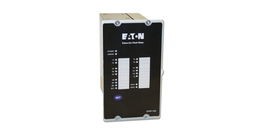
Eaton’s Arc Flash Relay (EAFR) provides reportedly unmatched switchgear protection. This relay reduces arc flash energy by quickly clearing the current feeding the arc. The sensitive light inputs with current permissive detection identify low power phase to ground arc faults. The EAFR works to prevent faults in medium and low-voltage switchgear, and the factory-installed Arc Flash Relay modules and sensors allow for simple integration into electrical assemblies.
Arc flash relay core features
Protection features
The EAFR system is a sophisticated micro-processor based arc flash protection system with combined current and arc sensing. Combined current and arc sensing provides an integrated dual trip criteria. It is designed to minimize the damage caused by an arcing fault (arc flash) by tripping the circuit breaker sourcing the fault current.
- Three phase instantaneous overcurrent elements (50P) (Permissive only with light input)
- Ground instantaneous overcurrent element (50G) (Permissive only with light input)
- Breaker failure (50BF)
Current sensing
The main units EAFR-110F and EAFR-110P each contain four current transformer inputs that provide sensing for the phase and ground instantaneous overcurrent elements. These elements act as a permissive for the light sensing inputs so that when they are incorporated into the scheme both current and light must be present to initiate a trip command. This current information can be shared with downstream modules as well.
Light sensing
Arc flash light can be collected by either point sensors or fiber loop sensors. Up to 12 point sensors or 3 loop sensors can be connected to each module. Light sensing can initiate a breaker trip independent of current if desired. Because point sensors are interconnected with copper wire they can provide a much better installation for Electrical OEM’s where the system can be fully wired and tested in the factory. Sensor wiring allows daisy chaining up to three sensors over a distance of 100 meters.
- Point sensors: Up to 12 sensors per module
- Fiber loop sensors: Up to 3 sensors per module
Relay outputs
- Four Trip Relays per module (7 mS)
- Two High Speed outputs (2 mS – EAFR-110P, EAFR-110F)
- System failure relay
Indication
- Power available LED
- System health LED
- Trip relay activation LED’s
- Sensor channel activation LED’s
- Overcurrent element pickup LED’s
Self monitoring
Complete system self monitoring provides the highest level of dependability by continuously monitoring all internal system functions along with external connections between modules, light sensors or loops and current transformers.
Breaker failure
The circuit breaker failure protection (CBFP) is initiated when a light signal and second trip criteria signal (e.g. overcurrent), if applicable, is active for above the set CBFP time of either 100 or 150 ms. The trip relay T2 and binary output BO1 will operate after the set time delay
Communications
Because of the simplicity of the system, all monitoring is done through contact outputs on the arc flash relay modules. The advantage of this approach is that cybersecurity issues are nonexistent.
Configuration
Easy configuration and setup with 4 dip switches to select one of many different standard sensor channel configurations for Light or Light & Current tripping.


