Siemens’ Tips for Panel Builders Series – Part 4: Control Panel Modeling in 3D


The manufacturing of control panels and system cabinets in particular incurs high expense and wastage when it comes to the wiring and mechanical processing of the cabinets. 3D planning offers a solution in terms of optimizing the work steps and avoiding the unnecessary waste of excess cable. For this purpose, the EPLAN range of products includes the Pro Panel software, which facilitates the 3D planning of control cabinets.
What does it offer you?
Apart from the purely 3D data, other helpful technical information is stored directly in the article macros of the Siemens devices. For example, you will find information in Pro Panel about the connections of the article to support the auto-routing function. In addition to the description and design of the connections, the global wiring diagram also stores their position in three-dimensional space as well as their routing direction. With the help of these specifications, the necessary cable lengths can be calculated to the exact millimeter directly in EPLAN on the basis of the wiring diagram project.
In addition, these values can be exported to a cable assembly machine in order to guarantee standard-compliant wiring to the exact cable length. You can show the cable-laying direction and connection designation directly in 3D by selecting View → Connection Directions or Connection Designations.
Apart from the wiring diagram, you will also find a drilling template in the Siemens article macros. These contain valuable information about the number, position and size of necessary penetrations on the mounting plate or door cutouts. This information can also be exported from EPLAN to a machine / robot, enabling all necessary penetrations to be transferred automatically to the mounting plate. You can make this visible in EPLAN by selecting View → Drill-hole view.
Then use our CAx Download Manager. This enables you to request our CAx data automatically, such as certificates, documentation, product master data and much more, for a number of articles at the same time. When your download is ready, you are notified by email containing a link to your individual download. Select the type of information “Product master data” if, for example, you require cable cross -sections or other technical specifications.
All necessary power loss data for control panel devices can be found in the Siemens Industry Online Support Portal.
On many accessory parts and basic units, mounting points are stored in the macros. These support you when assembling two components in 3D. In this way, the risk of errors can be minimized and precise placement is made possible.

Allied Electronics & Automation continues to enhance its expert advice website offerings for April, adding six articles to their expanding topic list in categories like industrial communications, industrial control, machine safety, motion control and sensing.

Allied Electronics & Automation is celebrating its 10-year anniversary with Siemens. Siemens first partnered with Allied in 2012 and Allied quickly demonstrated value by providing Siemens with access to untapped market segments and dedicated customer service support teams and surpassing sales goals. In response, Siemens quickly expanded Allied’s access to its product portfolio.

Hammond Manufacturing is pleased to announce the appointment of John Eberhart as the Territory Sales Manager for the Northern Midwest region of the United States in their Rack Mounting Solutions division. John’s extensive industry experience will be instrumental in the expansion of Hammond’s market presence and the promotion of business within his territory. John Eberhart has a demonstrated history of revenue growth and more than twenty years of experience in the data center and outside plant industries. John is also a current member of the TIA Edge Datacenter Working Group providing Hammond with leading developments for TIA standards.

Allied Electronics & Automation supplies hardware for Phoenix Contact’s new PLCnext Edge Gateway software, a state-of-the-art IIoT edge computing solution designed for data collection in demanding industrial and manufacturing environments. The new PLCnext Edge Gateway software is the latest addition to Phoenix Contact’s PLCnext Technology platform and enables industrial automation and control customers to transmit data from any industrial system to any cloud without having to invest capital to adapt legacy infrastructure.

The International Society of Automation (ISA) announces the fourth edition release of its Control Systems Engineering Exam Reference Manual: A Practical Study Guide—updated to cover the new, 2019 Principles and Practice of Engineering (PE) Control Systems Engineering (CSE) exam specifications developed and administered by the National Council of Examiners for Engineering and Surveying (NCEES).

In this episode, Tom Ballou, the Sales and Marketing Manager at Hammond Manufacturing, shares expert insights into factory modified electrical enclosures, the custom products available through RS, and Hammond’s unique value.

Allied Electronics & Automation continues to enhance its expert advice website offerings for April, adding six articles to their expanding topic list in categories like industrial communications, industrial control, machine safety, motion control and sensing.

Allied Electronics & Automation is celebrating its 10-year anniversary with Siemens. Siemens first partnered with Allied in 2012 and Allied quickly demonstrated value by providing Siemens with access to untapped market segments and dedicated customer service support teams and surpassing sales goals. In response, Siemens quickly expanded Allied’s access to its product portfolio.

Hammond Manufacturing is pleased to announce the appointment of John Eberhart as the Territory Sales Manager for the Northern Midwest region of the United States in their Rack Mounting Solutions division. John’s extensive industry experience will be instrumental in the expansion of Hammond’s market presence and the promotion of business within his territory. John Eberhart has a demonstrated history of revenue growth and more than twenty years of experience in the data center and outside plant industries. John is also a current member of the TIA Edge Datacenter Working Group providing Hammond with leading developments for TIA standards.

Allied Electronics & Automation supplies hardware for Phoenix Contact’s new PLCnext Edge Gateway software, a state-of-the-art IIoT edge computing solution designed for data collection in demanding industrial and manufacturing environments. The new PLCnext Edge Gateway software is the latest addition to Phoenix Contact’s PLCnext Technology platform and enables industrial automation and control customers to transmit data from any industrial system to any cloud without having to invest capital to adapt legacy infrastructure.

The International Society of Automation (ISA) announces the fourth edition release of its Control Systems Engineering Exam Reference Manual: A Practical Study Guide—updated to cover the new, 2019 Principles and Practice of Engineering (PE) Control Systems Engineering (CSE) exam specifications developed and administered by the National Council of Examiners for Engineering and Surveying (NCEES).

In this episode, Tom Ballou, the Sales and Marketing Manager at Hammond Manufacturing, shares expert insights into factory modified electrical enclosures, the custom products available through RS, and Hammond’s unique value.

Allied Electronics & Automation continues to enhance its expert advice website offerings for April, adding six articles to their expanding topic list in categories like industrial communications, industrial control, machine safety, motion control and sensing.

Allied Electronics & Automation is celebrating its 10-year anniversary with Siemens. Siemens first partnered with Allied in 2012 and Allied quickly demonstrated value by providing Siemens with access to untapped market segments and dedicated customer service support teams and surpassing sales goals. In response, Siemens quickly expanded Allied’s access to its product portfolio.

Hammond Manufacturing is pleased to announce the appointment of John Eberhart as the Territory Sales Manager for the Northern Midwest region of the United States in their Rack Mounting Solutions division. John’s extensive industry experience will be instrumental in the expansion of Hammond’s market presence and the promotion of business within his territory. John Eberhart has a demonstrated history of revenue growth and more than twenty years of experience in the data center and outside plant industries. John is also a current member of the TIA Edge Datacenter Working Group providing Hammond with leading developments for TIA standards.

Allied Electronics & Automation supplies hardware for Phoenix Contact’s new PLCnext Edge Gateway software, a state-of-the-art IIoT edge computing solution designed for data collection in demanding industrial and manufacturing environments. The new PLCnext Edge Gateway software is the latest addition to Phoenix Contact’s PLCnext Technology platform and enables industrial automation and control customers to transmit data from any industrial system to any cloud without having to invest capital to adapt legacy infrastructure.

The International Society of Automation (ISA) announces the fourth edition release of its Control Systems Engineering Exam Reference Manual: A Practical Study Guide—updated to cover the new, 2019 Principles and Practice of Engineering (PE) Control Systems Engineering (CSE) exam specifications developed and administered by the National Council of Examiners for Engineering and Surveying (NCEES).

In this episode, Tom Ballou, the Sales and Marketing Manager at Hammond Manufacturing, shares expert insights into factory modified electrical enclosures, the custom products available through RS, and Hammond’s unique value.

This webinar presented by Beth Lessard and Keith Cordero will be highlighting three Panduit solutions that will optimize network equipment and cabling to ensure that your spaces are efficiently and properly managed to support ever-evolving business needs of today and beyond. Products that will be featured include PanZone TrueEdge Wall Mount Enclsoure, Cable Managers, and Adjustable Depth 4-Post Rack.
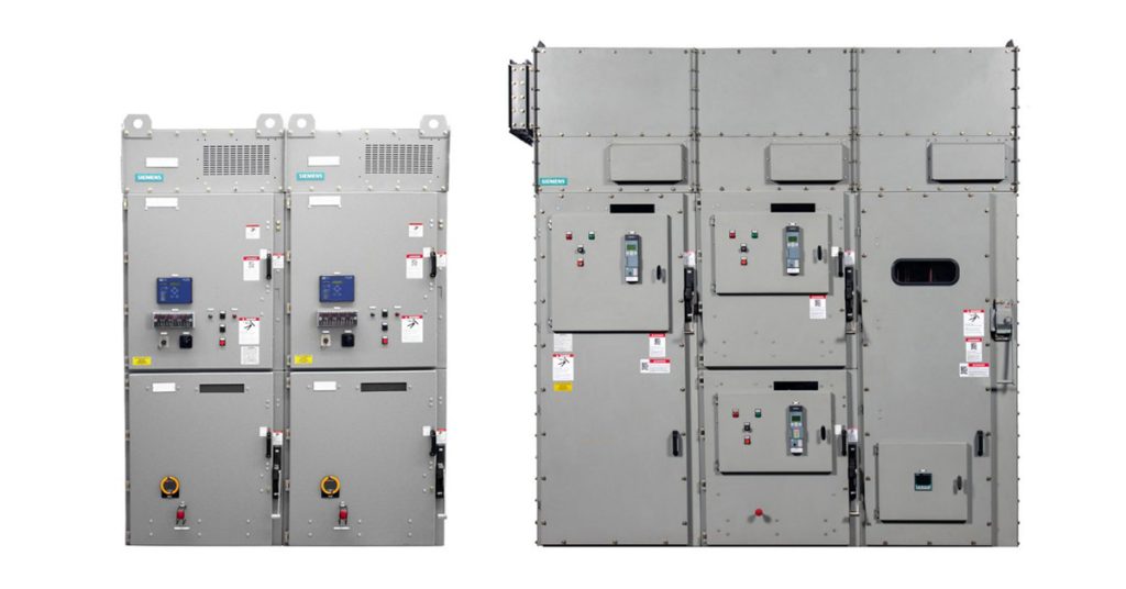
The Siemens SIMOVAC medium-voltage non-arc-resistant and SIMOVAC-AR arc-resistant controllers have a modular design incorporating up to two 12SVC400 (400 A) controllers, housed in a freestanding sheet steel enclosure. Each controller is UL 347 class E2, equipped with three current-limiting fuses, a non-load-break isolating switch, and a fixed-mounted vacuum contactor (plug-in type optional for 12SVC400). The enclosure is designed for front access, allowing the equipment to be located with the rear of the equipment close to a non-combustible wall.

Power is vital to production, and well-designed control cabinets are key. Allied Electronics & Automation offers a comprehensive collection of control cabinet solutions including PLCs, HMIs, contactors, miniature circuit breakers, terminal block connectors, DIN-rail power supplies, pushbutton switches, motor starters, overloads, power relays, industrial Ethernet switches and AC drives engineered to keep your operations running safely, reliably and efficiently.
Learn more HERE.
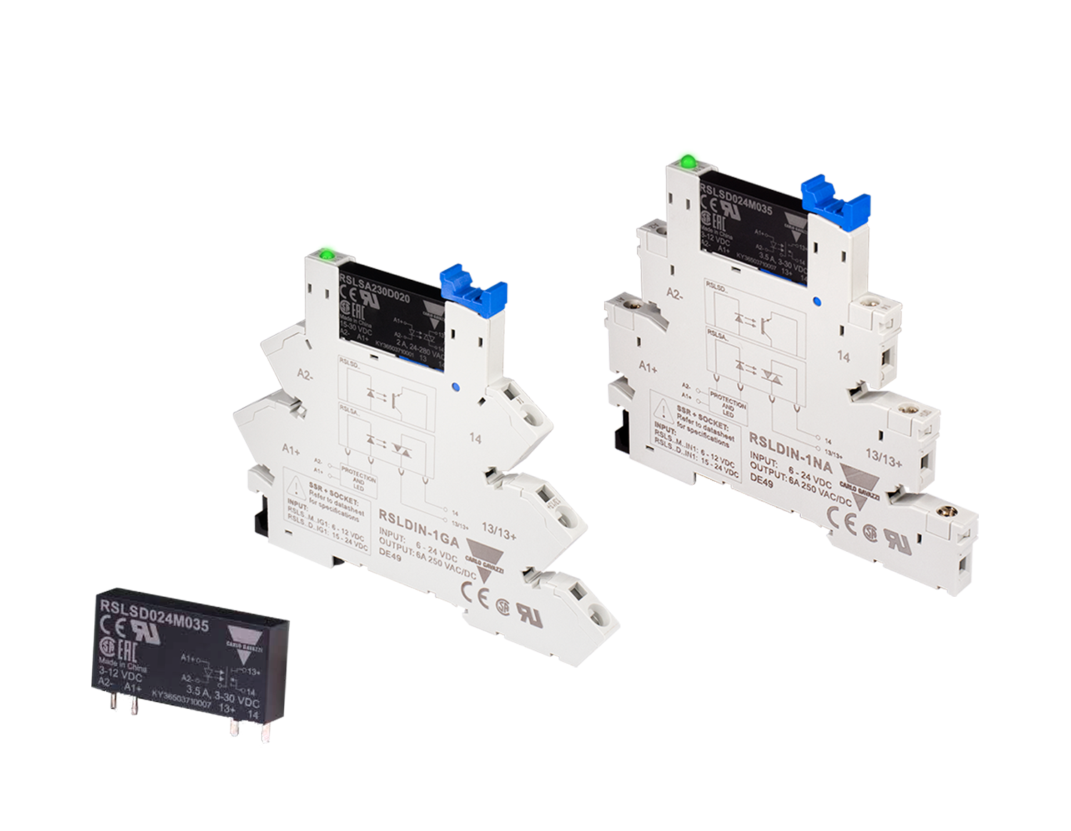
Carlo Gavazzi Automation has launched its RSLS Series of Ultra-Slim Solid State Relays designed for low power DC and AC loads. The RSLS Series features a 1-pole, ultra-slim 5mm wide design, ideal for low power loads. The compact form factor aligns with industry standards, allowing the RSLS to replace electromechanical relays with the same footprint,… Read More…

May 6, 2025 AS-Interface enhances Efficiency and Flexibility in Silos Companies worldwide are relying on simple wiring and automation technologies to improve plant efficiency and availability. The proven AS-Interface technology offers high reliability, noise immunity and comprehensive diagnostic capabilities. Typical applications include wheat and grain silos, plants for concentrated and compound feed, and mills. In… Read More…