Considerations for Selecting an Electrical Enclosure Cooling Solution
Optimal air circulation is key to protecting critical components
October 10, 2024
By Lucas Faulkner and Matthew Roberts, Pfannenberg, Inc.
Electrical enclosures house critical components that generate heat during operation. Proper air circulation can make or break an electrical enclosure. Inadequate air circulation can lead to isolated temperature accumulation, running the risk of system malfunctions, reduced component lifespan, and compromised reliability.
To select the best cooling solution for an electrical enclosure, consider such factors as the unit’s proximity to operators, whether it will be installed in a temperature-controlled facility, and the type of airflow inside the enclosure. Read on for an overview of electrical enclosure cooling challenges, a review of tools that can be used to simulate and optimize airflow patterns within the enclosure, and considerations for designing electrical enclosures for optimal air circulation.
Electrical enclosure basics and challenges to proper heat dissipation
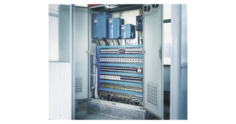
Electrical enclosures serve as protective housings for power supplies, circuit boards, drives, motors, and electrical components. The enclosures must maintain optimal operating temperatures to operate these components efficiently, avoid the need for costly replacement, and get the longest possible lifespan from expensive equipment.
Unfortunately, as manufacturing floor space has become increasingly limited, companies have begun to install smaller electrical enclosures. This poses serious challenges to the effective air circulation necessary to dissipate the heat generated by electrical components in the enclosure. This dissipated heat needs to either be cooled or carried outside the enclosure to the ambient environment to prevent temperature-related issues like thermal stress, accelerated aging, and potential component failure. Proper air circulation also ensures a uniform distribution of temperature within the enclosure, reducing the likelihood of localized hot spots.
Cooling electrical enclosures maintains the optimal operating temperature and prevents potential damage to electronic components. Common cooling strategies for managing this thermal challenge include incorporating fans that utilize open loop cooling, or using closed loop cooling, such as heat exchangers and air conditioning systems designed specifically for enclosures.
Enclosure air cooling considerations
Before selecting the electrical enclosure cooling solution, begin by evaluating the environment in which the unit will be installed. If you are exhausting heat out of the enclosure in proximity of any operators, install baffling to avoid the air hitting the operators. The solution can also be positioned away from the operator.
Next, determine if the solution is being installed in a temperature controlled facility. This is important, because the heating, ventilation and air conditioning (HVAC) systems cooling the facility must account for heat rejected into the ambient environment; failure to take this into account may cause overheating because the enclosure’s heat becomes rejected into the facility. Working with a mechanical contractor can establish if the heat load inside the enclosure can be exhausted into the facility. In certain scenarios, an air-to-water heat exchanger can be more beneficial, as it rejects heat into the water where a liquid chiller can handle the additional heat load.
Another factor to consider is airflow inside the enclosure. Since enclosures are becoming more densely packed, companies must maintain proper and consistent airflow to prevent hotspots or potential condensation from overcooling.
Use computational fluid dynamics to simulate and optimize enclosure airflow patterns
To ensure that the enclosure cooling solution meets application-specific needs, consider using a computational fluid dynamics (CFD) analysis to simulate and optimize airflow patterns within the enclosure. The tool can be used to identify potential hotspots within the enclosure, verify that temperature distribution within the enclosure is manageable for components, check the potential for pressure pockets between components, and even determine if specific components are being overcooled.
Below are three CFD analysis test scenario examples. The scenarios feature a variable frequency drive (VFD) positioned in front of an air conditioner’s (A/C’s) outlet to show the impact on airflow, because the VFD is the component that would be creating the most heat in an enclosure.
The scenarios were designed to examine a common misconception made by cooling solution designers who often mount the most sensitive/highest heat generating components closest to the A/C unit to ensure it is properly cooled, without understanding that this placement will create disturbances in airflow.
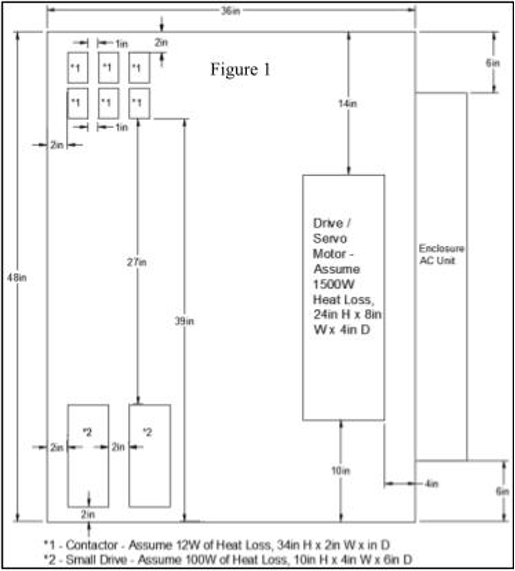
Figure 1 The test scenarios were designed to push the drive deeper into the cabinet for each scenario away from the cold air outlet on the bottom of the AC unit. The other components were mounted in positions to show potential hotspots that could be generated. Drives inside of enclosures typically include an internal fan or heat sink to reject the heat from the drive.
The density of the lines and arrows of airflow paths mean more airflow is traveling in that direction. The colors of the lines are representative of the temperatures of the air travel – blue is the coldest air and red is the hottest air.
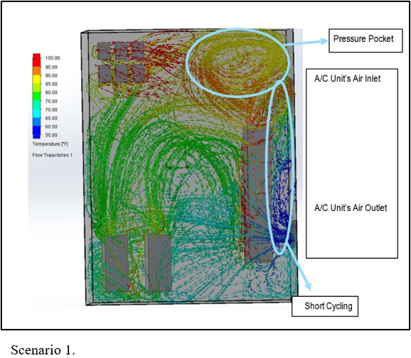
In Test Scenario #1, the blockage was 4 inches from the cool air outlet. In this configuration, a majority of the cold air leaving the A/C unit would be blocked by the large drive in front of it, resulting in it cycling right back into the A/C unit’s fan inlet. The cooler air being redirected immediately back into the cooling unit “tricks” the A/C unit into believing setpoint has been reached and will shutoff immediately. Once the heat from the other part of the cabinet rises, the A/C unit will turn on again. The short interval between the A/C turning off and on is referred to as short cycling.
This means that the A/C unit is failing to remove the heat from the cabinet as well as placing a strain on the A/C unit’s compressor for it to turn on and off in consecutive use, which could lead to potential icing inside of the A/C unit’s air outlet. A pressure pocket forms in the top right hand corner of the enclosure due to the drive’s exhaust being sucked directly into the A/C unit’s fan inlet and blocking the airflow path for the hot air to return to be cooled by the A/C unit.
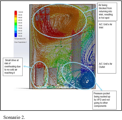
In Test Scenario #2, the blockage was pushed to 8 inches of total distance between the A/C unit’s air outlet and drive. While the unit still risks short cycling with cold air being pushed back into the evaporator fan inlet, increased airflow reaches the other side of the enclosure. A smaller pressure pocket forms in the lower right corner where air is drawn into the large drive’s fan, leading to improper airflow inside the cabinet. The large drive’s fan blocks airflow to the A/C unit’s air inlet, causing a large pressure pocket of hot air to form, which prevents hot air from escaping.
This could lead to overheating of the contactors due to insufficient cooling. The two smaller drives in the corner are at risk of overheating, with the left one vulnerable as the right drive takes in cold air before it reaches the left one.
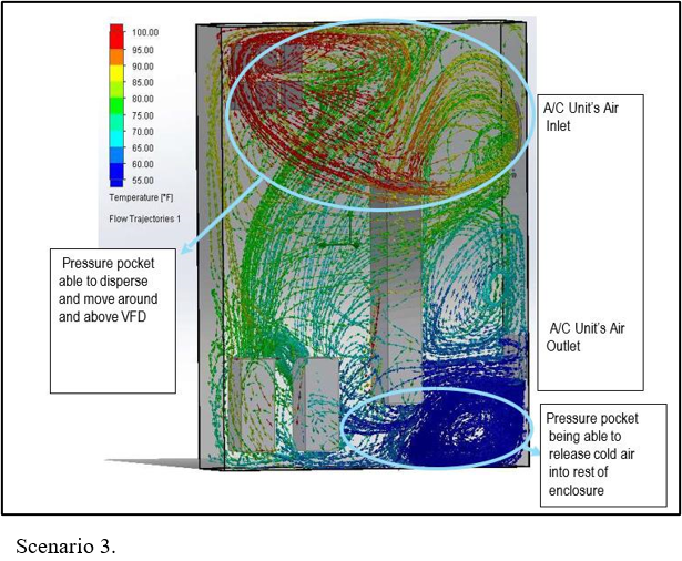
Test Scenario #3 pushes the blockage to 12 inches of total distance between the A/C unit’s air outlet and drive. This unit has the lowest chances of short cycling out of the three scenarios. Additional airflow can get across and reach the other side of the enclosure because the pressure pocket in the lower right corner disperses under the drive and to the rest of the enclosure.
The large pressure pocket of hot air that formed in Scenario 2 is completely dispersed; the airflow path can travel at the top and around the drive while still being able to cool the large drive. The airflow from the two smaller drives can push cooler airflow near the contactors and is able to carry the heat from them and bring it to the A/C unit.
Scenario #3 presents the least possible likelihood of short cycling cold air being redirected into the A/C unit and all components have airflow going to them. Scenario #1, had the highest chance of short cycling overall which would cause the unit to shut off early and not cool the enclosure to the desired temperature. Scenario #2 featured a large pressure pocket of hot air that would not be able to cycle correctly and would end up causing most of the contactors to overheat.
While these scenarios are simulated, and may not exactly replicate real world conditions, they can be used as best practices when designing the enclosure layout. For example, the scenarios showed that, as the blockage was pushed further out, there was better airflow in the enclosure, but it became apparent that the large drive’s exhaust air was blocking airflow in the cabinet. This is why components with larger fans internally should typically be mounted farther away from the A/C unit to help cycle airflow throughout the enclosure.
Another common misconception is that since the large drive is the most sensitive component, it would need to be mounted as close as possible to the A/C unit to receive the coldest air. This is incorrect, because it would end up restricting airflow for the other components inside of the enclosure. Instead, it should be mounted farther away from the A/C unit. This would allow for airflow to travel towards it and would support a full circular motion of airflow throughout the enclosure.
Other design considerations
When designing electrical enclosures for optimal air circulation, engineers should consider the following:
Ventilation and cooling systems
Integrating ventilation and cooling systems, such as fans or heat sinks, can complement the effects of component spacing. These systems can further enhance heat dissipation within the enclosure. Using enclosure fans inside electrical enclosures are a great way to help move air within the enclosure. In scenarios where possibility of repositioning components is limited, enclosure fans can be installed to help ensure air is reaching all points of the enclosure.
Enclosure material and color
In outdoor applications or hotter environments, heat transfers into the enclosure from the hotter ambient air through the metal enclosure or from the sun hitting the enclosure. Using a darker color absorbs more heat from the sun, while use of a light color reflects the heat from the sun and has less likelihood of solar loading. Every metal has a heat transfer coefficient and can affect the amount of heat transfer from the environment into the enclosure and vice versa. Insulation can be used on the inside of the enclosure to help prevent the ambient environment’s heat transfer from affecting the enclosure.
Alternatively, a sun roof can be used to keep the sun from directly hitting the enclosure to prevent solar loading.
Enclosure mounting style
The amount of surface area of the enclosure can affect the amount of heat transfer to the environment if the ambient environment is cooler than the enclosure, or the amount of heat transfer to the enclosure if the ambient environment is hotter than the enclosure. Surface area is often overlooked as a factor that can lead to large amounts of unplanned heat inside the cabinet due to heat transfer from the ambient environment. For example, there is no need to factor the heat transfer from the back of the enclosure if the enclosure is mounted up against a wall.
Achieving a better enclosure system design
To ensure smooth and successful operations, companies can strategically space and position components within electrical enclosures to enhance air circulation and mitigate hot spots. Proper spacing strategies empower companies to optimize air circulation, effectively dissipate heat, and improve overall system performance. Use of CFD analysis helps companies design enclosures that factor in enclosure temperature and air flow. Other considerations, like integrating ventilation and cooling systems, enclosure color, materials, and mounting style, all play a part in achieving the best overall system design.