Weschler Instruments: Using DC Current Shunts
March 16, 2021
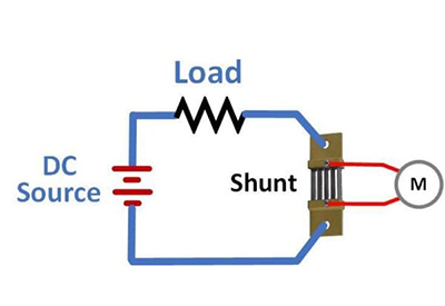
A DC current shunt is a specialized resistor used to measure high currents. The shunt is wired in series with a heavy load, such as a DC motor, battery charger, heater, plating bath or smelter pot line. A DC voltmeter is connected to the shunt in a 4-wire (Kelvin) configuration. The shunt has bolt holes or studs for the heavy wires and small terminals for the meter connections. The meter leads don’t carry high current, so they are a finer gauge than used in the load circuit. The preferred location for the shunt is on the grounded side of the load. This minimizes the voltage present at the shunt and meter connections.
Most shunts are made from manganin, an alloy that is 84% copper, 12% magnesium and 4% nickel. This material has an extremely low temperature coefficient of resistance, only 0.0015%/degC (15ppm/°C). For comparison, the TC of copper is 0.4%/°C. Shunts are specified for a 50mV, 75mV or 100mV drop at full-scale current. 50mV shunts are generally preferred since they have lower power dissipation and therefore less self-heating. For continuous operation, manufacturers generally recommend that shunts be limited to less than 2/3 of the rated current.
Shunt Installation
Large shunts are designed for direct mounting to bus bars. Care should be taken not to stress the shunt element during installation and to allow some movement for thermal expansion. Bus bars should be anchored to prevent excessive movement that stresses the shunt element during a current surge or short circuit. Some smaller shunts include an insulating base to simplify mounting to a panel or enclosure. The typical commercial shunt accuracy is 0.25% of reading.
For stable operation, the temperature at the center of the manganin blades should be less than 80°C. At temperatures above 80°C, the manufacturer may specify a derating factor to permit operation at a lower current level. A temperature above 140°C will cause a permanent change in manganin resistance, so 125°C is generally considered the maximum safe limit. Proper mounting helps minimize the temperature rise. To facilitate convection cooling, the shunt should be mounted in an open space with blades in a vertical position. If the shunt is in a cabinet or restricted space, forced air cooling may be needed. For shunts with the same amp rating, a larger size model will better handle heat dissipation and overloads.
Many meters used in shunt applications are scaled to display amps, although they are measuring voltage. A ‘shunt-rated’ DC ammeter is a voltmeter calibrated and scaled for a particular shunt current and full-scale voltage drop (e.g. 100A, 50mV). A 100 amp, 50mV shunt has a resistance of 0.0005 ohms (500μΩ). A digital meter used to monitor voltage drop across a shunt typically has an input resistance of 1MΩ or greater. Current flow in the meter leads is negligible, so the meter ‘load’ does not affect the measurement accuracy. For analog meters, the current flowing in the meter leads is small, but not negligible. The meter’s input resistance is usually between 6.5 and 50 ohms, depending on model.
Factory calibration of analog meters assumes 0.065Ω total lead resistance. This is equivalent to about 10 ft of #18AWG or 16 ft of #16AWG wire. Longer leads or finer wire with higher resistance will cause the meter to read low. For example: #20AWG wire has a resistance of around 10mΩ/ft. If the meter is located 50ft from the shunt, #20 wire introduces a total lead resistance of 1Ω, or 0.935Ω more than the meter is calibrated for. The additional lead resistance will cause a meter with 7Ω resistance to read 12% low. This is a far greater error than the ¼% shunt accuracy or a 1-2% analog meter accuracy. At the same distance, a 40Ω meter with #16 leads would read less than 1% low. In an application where the use of heavier leads is not feasible, the analog meter can be ordered with special calibration to compensate for the extra lead resistance.
In addition to analog and digital meters, other instrumentation can be used to monitor voltage across a DC shunt. A signal conditioner is sometimes employed to convert the millivolt signal for transmission to a remote location or interface to process control equipment. A typical example changes 0-100mV into a 4-20mA loop current. One benefit of this scheme: a broken connection can be easily detected. A recorder or data logger will capture and store readings for future examination. In applications where the current changes faster than can be seen on an analog or digital meter, a data logger (or meter with internal data logging) can sample at a higher rate.
DC current shunts provide a simple means to monitor high current circuits. Various instruments are available to measure the shunt output. Careful consideration of a few key factors will lead to a successful installation.
![]()
https://www.weschler.com/blog/using-dc-current-shunts/#more-61184

