Insulation Testing: Megohmmeter or Hipot Tester

January 19, 2021
There are two common methods for performing insulation resistance testing on cables, wiring and electrical equipment. One uses a megohmmeter to measure insulation resistance. The other uses a hipot tester to check for insulation breakdown. Both apply a high voltage, either ac or dc, to the device under test (DUT) and measure the resulting current flow.
Megohmmeters
A modern megohmmeter (or megohm meter) applies a dc voltage to a DUT and measures the dc current (nanoamps or microamps). Applying Ohms Law, the corresponding resistance value is then shown on the meter’s analog or digital display. This instrument is often called a megger, which is a term trademarked by the Megger Group in 1907.
In a typical megohmmeter, the user can select from several voltage levels. For cables or equipment with rated voltage up to 500V, the maximum dc test level is usually twice the rated voltage. Above a 500V rating, the maximum level is closer to the rated voltage (e.g. 5000V for a 4100V system). The equipment manufacturer may have more specific test recommendations.
Due to capacitance and dielectric effects in the DUT, it takes time for the reading to stabilize after the voltage is applied. Initially, the reading is dominated by capacitance charging. Absorption currents may be significant for 20 seconds or more. Usually, IR readings are made after 60 seconds to allow these effects to settle out.
Techniques
Two techniques can aid in insulation condition assessment. The first is to apply the voltage in increasing steps. Degraded insulation will show a declining IR value as the test voltage increases. For accurate results, dwell time at each step should be controlled. To make this an easy test, some megohmmeters include a function to automatically step up the voltage at programmed intervals.
Another assessment technique is to compare IR readings with previous test results. Since the megohmmeter uses a very low test current, it does not damage the insulation. Periodic IR testing will identify insulation degradation over time and the need for preventive maintenance. An accurate comparison requires measurements at the same voltage and dwell time. Moisture affects the IR readings, so care should be taken to perform the tests under similar temperature and humidity conditions.
Parameters
Two parameters derived from insulation resistance measurements are dielectric absorption ratio (DAR) and polarization index (PI). Advanced digital megohmmeters have dedicated functions to measure and display these parameters. DAR is the IR at 60 seconds divided by the IR at 30 seconds. A value less than 1 shows the resistance is decreasing with time, which indicates a failing DUT. The polarization index is used on motors and generators to assess the amount of impurities in the windings and their cleanliness. PI is the IR at 10 minutes divided by the IR at 1 minute. Some equipment standards specify minimum PI values. A ratio greater than 1.5 is generally adequate.
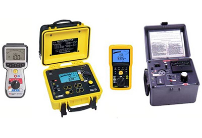
Handheld megohmmeters that source up to 1000V are available from several manufacturers. Portable units can supply up 15kV. Multi-purpose instruments combine IR measurements with other test functions, such as a multimeter. This photo shows a typical handheld megohmmeter, portable megohmmeter, megohmmeter/DMM and hipot tester.
Hipot Tester
A hipot (short for high potential) test determines the ability of electrical insulation to withstand normally occurring over-voltage transients. The hipot tester applies high voltage to the insulation barrier of the DUT and verifies there is no breakdown. It is a simple pass/fail test performed as a type test on a representative sample unit or as a routine production test. Maximum allowed leakage is usually in the range of 0.1 to 5mA, or as specified in the test standard. The actual leakage value for each DUT may be recorded for quality assurance.
Many standards (such as IEC 60950) specify an ac test voltage that is twice the operating voltage plus 1000V. Most allow the use of either ac or dc voltage. The test setup and procedures are identical for ac and dc, although the dc level should be equal to the ac voltage peak. The test time is normally 1 minute, but in some situations, such as high volume production testing, a shorter test time may be permitted at a higher voltage.
Typically, a hipot test is performed on the mains wiring of electrical equipment. One lead of the tester is connected to safety ground (earth ground). The other lead is connected to the line and neutral power leads. Often the hipot tester has a built-in ac receptacle to make these connections (as shown in the photo).
If the circuit under test has a power line filter, an ac hipot tester may indicate a failure due to current flow to earth thru the Y capacitors. The safety standard usually allows the user to disconnect these capacitors prior to testing or increase the upper current limit to compensate for the additional leakage. Alternatively, a dc test voltage can be used. Most hipot testers also include a low limit to ensure the test fails if the DUT is not connected or the test is interrupted. Unlike megohmmeters, which are usually battery-powered, almost all hipot testers require ac power.
In summary, insulation resistance is typically a field measurement to assess insulation quality. Hipot testing is usually a safety check performed in the factory to verify the product design and manufacturing process. This difference determines whether a megohmmeter or hipot tester is the appropriate insulation testing instrument.
![]()
https://www.weschler.com/blog/insulation-testing-megohmmeter-or-hipot-tester/


