5 Essential Elements of a Quality Feedback Cable
November 10, 2020
By Jeff Kardell, KEB America
Using a quality feedback cable is critical to maximizing performance in servo applications. As the saying goes, “A chain is only as strong as the weakest link.” It does not make sense to invest a lot of money in a high-performance servo motor, servo amplifier, and planetary gearhead and then cut corners with an inferior feedback cable since the entire system performance will suffer.
At the time of writing, our longest successful servo installation uses a 100 meter (EnDat) cable. How can you effectively transmit a 5V signal the length of a football field?
It is only possible with a high-quality cable that keeps out unwanted noise and interference. Today, we will take a look at five aspects of a quality feedback cable that you should keep in mind when choosing a solution for your application.
1. Utilize Shielded Twisted Pairs
Most position feedback systems will utilize differential signal pairs which provide benefits for long cable runs and noise immunity. A differential pair includes the primary signal (e.g., 0 …5V signal for TTL) and the complement or opposite of that signal. In theory, by twisting these signal pairs together, their magnetic fields will cancel each other out and reduce crosstalk from other pairs. A shield is then placed over each conductor pair to further prevent external EMI from coming on to the conductors.
2. Utilize Overall Shield Over All Conductors
Next, a second overall shield, preferably braided, is placed over all conductors in the feedback cable. This type of shielding again helps to prevent EMI from entering the cable. This is especially important since the feedback cables are likely running in a panel with high power and VFD switching transistors.
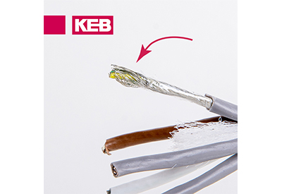
The picture below shows a feedback cable that utilizes both shielded twisted pairs – as well as a braided shield over the entire cable. The overall shield is connected to ground and provides a path to drain high-frequency noise from the feedback system.
3. Tough Sheath Material
The material of the feedback cable is also critical. It is important to have a sheath that consists of an abrasion and cut-resistant material. In manufacturing environments, it is common to have many sharp edges and materials that the cable can catch on. Using a material that can withstand those conditions is highly recommended. KEB’s standard feedback cables include an outer sheath made of Polyurethane, which is extremely wear-resistant and mechanically tough for harsh environments, while still being flexible and age resistant.
There are other cable sheath materials available if you plan to be around chemicals or oils that would degrade the Polyurethane material.
4. Bend Radius and Cable Flex
The bend radius is the radius at which a feedback cable can be bent without damaging it – and should be specified by the manufacturer. To ensure reliability and a long service life of a cable, you must make sure that the bend radius of your application is greater than the recommended minimum bend radius of the cable you choose.
In some applications like a gantry or robotic system, the feedback cable must bend repeatedly as the machine is moving. A user should check that the selected feedback cable is capable of this type of application. Manufacturers should list the cable’s “bending cycles” which provides information on the expected lifetime of the cable in dynamic applications. In general, KEB encoder cables are robotic grade and support a high number of bend cycles.
5. Connectors
There are many options for connectors on feedback cables, and it is a critical component of your selection. Screw-in connectors can be utilized to reduce strain on the cable in small installation spaces. As a rule of thumb, a prefabbed cable with terminated connectors is always preferred for noise immunity. Terminated connectors also make for a quicker installation and reduce the likelihood of mis-wiring in the field.
KEB’s feedback cables are equipped with connectors to ensure compatibility with KEB drive and motor products. Although it is possible to terminate your own connectors from cable stock, it is likely faster and easier to purchase a prefabbed cable that has been QA tested already.
Adding Connectors in the Field
In certain situations, purchasing a pre-fabricated cable will not be an option for your application. For example, perhaps a special connector is required, or a connector must be changed in the field. In this case, either the motor or drive side connector can be modified. Remember these principles when connecting a feedback device to a KEB drive:
- – The outer shields are tied to the metal connector housings on both ends. These housings connect to the Earth ground.
- – The internal twisted pair shields are connected on the drive side to 0V common. The internal shields on the motor/encoder side are clipped short and not connected.
- – Always follow the instructions of the connector manufacturer when modifying a feedback cable. This might require a solder connection or specially crimped connectors.
- – One complete run is optimum. Avoid terminal strips and “breakout” boxes whenever possible. These disrupt the EMI shielding and act as an EMI entry point.
Use a Good Feedback Cable and Sleep Better at Night
People use inferior feedback cables for a variety of reasons including cutting costs, the need to splice connectors or roll your own, or even “I found an old cable in R&D”. But don’t get caught in this trap – remember the above principles and use high quality cabling.
![]()
https://www.kebamerica.com/blog/5-essential-elements-of-a-quality-feedback-cable/


