Allied Ask The Expert: Industrial Control Panel Design

October 20, 2020
In this edition of Allied’s “Ask The Expert” series, the topic is industrial control panel design with Jim Davis, director of advanced solutions & technical support at Allied Electronics & Automation. Jim leads the technical support and application engineering teams Allied, collaborating with customer support and sales teams to ensure a best-in-class experience for the company’s customers. Jim has an extensive background in electronics and engineering with almost three decades of experience at companies like Allied, Schneider Electric and Acme Manufacturing.
When creating control panel designs for industrial control systems and aligning the panels, how important is wiring to the overall success of the job?
In terms of laying out industrial control panels, wiring plays an absolutely critical role in effective design and construction. It’s crucial that the task be completed in a manner that fits industry standards.
What are some ways to ensure you’re creating these designs effectively and efficiently, especially for systems with small to midsize PLCs that control machines and equipment?
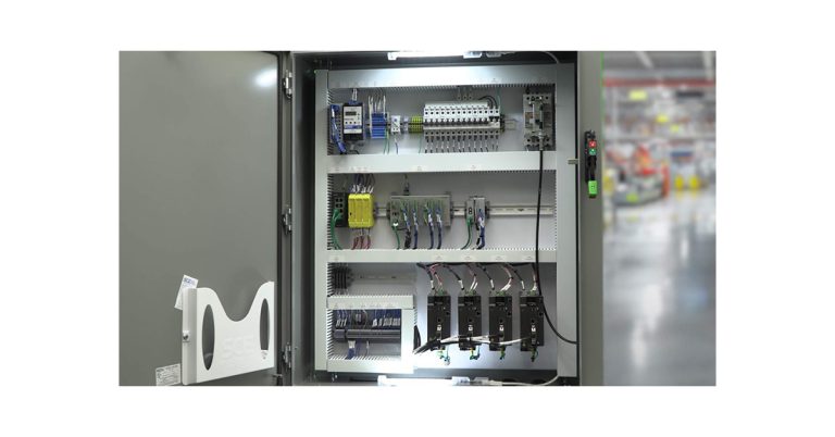
First, separate the power and control wiring so there’s less of a chance that electrical noise could affect control signals. You can accomplish this by laying out the panel in such a way that power and control are in separate sections. All power fuses, motor starters and variable frequency drives should be grouped on the same side of the panel as the incoming power. All the low-voltage control components should be placed on the other side. Take note that contactors and variable frequency drives will still need control wiring. You should map out a path for the control wires to get to the power side, while each remains separated.
Second, separate field wiring from internal wiring by placing terminal strips so that there are wire ducts for each. Not only does this simplify the field wiring, it makes it easier if you have to disconnect the wiring when shipping the machine. To most effectively achieve this separation, consider how the field wiring going to the machine will route into the panel. Decide if you will use conduit, cables or wireway and if the wiring will enter from the top, bottom or side. Don’t lose sight of the first best practice and figure out how best to keep power and control wiring separated.
Next, determine the right sized wiring duct. This is important because wiring ducts can consume a significant amount of space in a panel, especially if you run extra ducts to separate power and control. A right-sized duct is one that’s neither under-filled nor over-filled and has space for easy access when wiring.
Fourth, provide adequate space for wire routing. It’s completely understandable if you’d be inclined to reduce the working space around components to shrink the overall size of the panel when you’re designing panel layouts in CAD. The problem is, you’ll still need sufficient room to fit your hands and tools into spaces. Once the panel is built, evaluate the space around various devices to help improve future designs. Also, if you’re working with larger wire you should leave enough room to route and bend them.
Fifth and finally, make sure to properly ground the panel and devices. To accomplish this, include a row of ground terminals in the panel and connect all ground wires there. You should also consider mounting a ground terminal adjacent to the disconnect and running a large ground wire between it and the ground terminal. This will make it obvious where to terminate the ground for the incoming power.
That’s a lot of great information! What are the national and international standards one should adhere to when creating these designs?
There are three in particular that I find useful. The first is NFPA79: Electrical Standard for Industrial Machinery. The official description is: “NFPA 79 provides safeguards for industrial machinery to protect operators, equipment, facilities, and work-in-progress from fire and electrical hazards.” It contains a wealth of helpful information and is an essential tool for anyone designing industrial controls & equipment. Another one is UL508A: the UL standard for the construction of Industrial Control Panels.
Finally, the CE specifications for Europe contain a mix of directives & standards. These include:
- 2006/42/EC Machinery Directive
- 2014/35/EU Low Voltage Directive
- 2014/30/EU Electromagnetic Compatibility Directive
- A long list of other standards for machine safety systems, risk assessments, guarding, ergonomics, etc. There are also separate standards for specific types of equipment.
Since you brought up Europe, are there any initial steps that should taken to ensure compliance there?
The best way to get started in the European market is to consult with a notified body. A notified body is an organization authorized by the European Union to assess the conformity of products. They can help you determine which particular directives and standards are applicable to your equipment and also educate you on methods for certifying your equipment.
For your own benefit, some of the Machinery Directive elements should be incorporated into your standard designs. They’re good practice and will help you create a more universal design.
Lastly, what are some good resources to consult for panel design and build?
We have a section of Allied’s Expert Advice content dedicated to industrial control panels, and we’ve partnered with both Schneider Electric and Eaton on industrial panel builder digital resource hubs. This should be a useful place to start.
![]()

