How To Build a Motor Starter in Accordance With UL 508A
March 5, 2020
By Scott Whitsitt, Product Application Engineer, Schneider Electric
UL 508A allows control panel builders to apply a UL label to their finished assemblies without having to run those assemblies through specific UL testing. As long as they adhere to the standard’s requirements, builders can put the UL label on the finished product and save money by not having to send it to UL for testing.
According to UL, the UL 508A standard applies to industrial control panels intended for general industrial use that operate from a voltage of 1000 volts or less. This standard also applies to industrial control panel enclosures and industrial control panels used for flame safety supervision of combustible fuel type equipment; elevator control; crane or hoist control; service equipment use and various other applications.
The first iteration of UL 508A stated that you must put a label and a short circuit current rating on the panel, but didn’t really explain how that rating should be applied in the field. Over time, as it went through another four or five iterations, the standard was made more rigorous. Its current iteration was published in 2018, at which point many of Schneider Electric’s customers began to ask us what they needed to do in order to adhere to it. Two years isn’t a long time in our industry, so the latest version of UL 508A is still fairly new.
Over the last few years, the requirements around UL-related documentation became more stringent. That means panel builders must be prepared to show the work they’ve done when building motor starters in accordance with UL 508A. Documentation is especially important during inspections, when builders are asked to verify exactly how they assembled and installed the motor starter – this is a key concern in the industry right now.
The Four Functions of Combination Starters
A motor starter is a contactor combined with a motor overload relay, while a combination starter also includes a disconnect and short-circuit protection. The most common type of packaged motor controllers, combination starters got their name due to the way they’re constructed and what combined functions they handle. National Electrical Code (NEC) Article 430 defines the required functions of combination starters, while UL specifies the tests and verifications that the components must pass before they can be listed as suitable for use for those functions.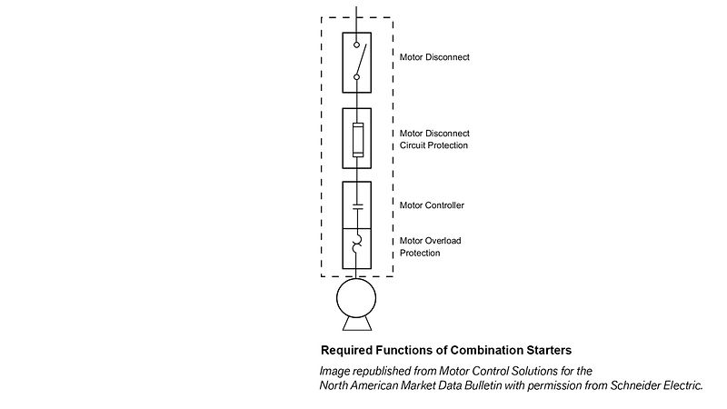
UL-defined combination starters include these four key functions, each of which can either be a separate device or incorporated into a single device:
- – A motor disconnect
- – The motor branch circuit protection
- – A motor controller
- – The motor overload protection (built into the assembly)
There are myriad ways to configure this combination, but in most cases the motor starters include:
- – A disconnecting isolation device (typically a switch);
- – some type of short-circuit protection (a fuse or circuit breaker);
- – a manual or automatic motor controller (a contactor or manual starter) and
- – the motor overload protection.
It’s important to note that motor overload protection is different than the overload protection that a typical circuit breaker provides. A circuit breaker is designed to protect the conductors that it feeds, but motor overload protection is designed to protect the actual motor.
Earning the UL 508A Label
There are numerous qualifications control panel builders must meet in order to be a UL 508A certified panel shop. One of the most talked-about yet most poorly understood of these is the requirement that panel builders specify the maximum short-circuit current that the panel can withstand on their UL 508A label. This requirement impacts the design and component selection for every panel the builder ships. Understanding this aspect of the control panel builder’s business provides Schneider an opportunity to increase our credibility and strengthen our role as a resource for our customers.
The amount of current that flows in a short circuit can be very high, due to the fact that it is a very low-resistance path for the current to flow. For example, the short circuit current can be in the tens of thousands—if not hundreds of thousands—of amps, whereas the device experiencing that current may only be designed to operate continuously at 25 amps. Because of this, a short-circuit current can be extremely dangerous and can create numerous hazards, including physical damage, fire, injury, or death. That’s why knowing how much short-circuit current a control panel can be subjected to without extensive damage is so important. This maximum current value is specified on the control panel’s label as the “short circuit current rating”, or “SCCR”.
 Once the control panel is installed, the NEC requires the end user to be able to document that the panel’s SCCR is greater than or equal to the amount of short circuit current the panel might be exposed to. From the panel builder’s standpoint, a higher SCCR on their panel gives their customers more confidence that the installation is safe and will be approved. It also means the control panel is likely to be suitable for more customers and applications. As always, there is a tradeoff: higher SCCR often means higher cost.
To determine an industrial control panel’s overall SCCR, the panelbuilder looks at the SCCRs of the individual components inside the panel. The lowest SCCR of any of these components is the limiting factor so that becomes the SCCR of the entire panel. UL 60947-4-1, the UL standard that applies to motor control components, sets out the minimum SCCR a component may have to be UL-listed as a stand-alone device. Every UL-listed component has this stand-alone SCCR printed on the label, and most manufacturers also provide that information in other documents, as well.
UL 60947-4-1 also recognizes that some components may be able to accommodate higher short circuit currents when they are applied in series with certain other components and allows manufacturers to test these assemblies of components and publish the results. Control panel builders may then use these “high fault” SCCRs to increase the overall SCCR of their panel. The UL-defined combination starters are one example of an assembly of components that can have a much higher SCCR as a whole than any of the individual components alone.
For example, let’s look at the components we might use to control a motor rated for 10HP at 460Vac. From the catalog, we would choose an LC1D25 contactor (controller function) and an LRD21 overload relay (motor overload protection function). Individually, the contactor and overload relay each have a stand-alone SCCR of only 5,000 amps but, if we add a circuit breaker to build a combination starter, that combination might have a higher SCCR.
To determine this, we consult Schneider Electric’s Motor Control Solutions data bulletin (8536DB0901R09/16). Table 18 of this bulletin indicates that by putting a circuit breaker rated at 60 amps or less ahead of an LC1D25 contactor, it is possible to obtain an SCCR for the assembly of as much as 85kA at 480Vac. Similarly, Table 42 tells us that an assembly of a circuit breaker and an LRD21 overload relay can have an SCCR as high as 65kA. If we select a BDL36040 circuit breaker – which has an 18kA interrupting rating – the combination starter now carries an overall SCCR of 18kA at 480Vac. Depending upon the type of combination starter and the specific components used, such SCCRs can go as high as 130,000 amps.
Combination Starter Construction Types
There are currently five different combination starter types, each of which incorporates a different set of aligned components. Types A, C and D are three-component solutions that usually include a fusible switch or circuit breaker (plus the contactor and motor overload relay). The Type E starter is a self-protected combination controller where all four functions are built into a single device (i.e., a “one device” solution). The Type F starter is a two-device solution that combines these functions, but is not self-protected.
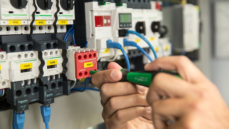 Type A through D combination starters are often considered “traditional” starters and use separate UL 60947-4-1-listed motor controllers and overload relays along with UL 98 listed disconnect switch and fuses, or a UL 489 listed circuit breaker, for the disconnect and short-circuit protection. Good examples of these are the Class 8538 & 8539 Type S combination starters, although IEC style controls may also be used and they do not need to be individually enclosed.
Type E combination starters perform all four motor control functions in a single device. This type of starter has been recognized by UL since 1990 and may take the form of either a manual or an electromechanical (remotely operated) motor starter. UL added a separate set of short-circuit and endurance performance tests to their 60947-4-1 standard specifically for the Type E self-protected category. The TeSys GV2 and GV3 are UL listed as Type E manual motor controllers and can be used to control motor branch circuits if manual-only switching of the motor is acceptable. TeSys U combination starters allow manual operation of the disconnect function, short circuit protection, motor overload protection and remote operation of the controller function.
Type F starters combine the manual UL 508A Type E manual starter with a UL 508A contactor but are not considered self-protected. This combination starter typically consists of a GV2 or GV3 manual starter and a TeSys D contactor. A separate overload relay is not required because the Type E starter has this function built in. Type F starters are evaluated under the same short-circuit tests as Types A through D.
Any Advantages or Disadvantages?
When selecting the best starter construction type for a particular application, there are always going to be tradeoffs across the A, C, D, E and F categories. There are advantages and disadvantages to each, and picking the right one will depend on the specific application and how the panel will be used. In most cases, the choice will come down to a trade-off between price and function. Here are some of the basic pros and cons of each:
- – Types A and C are basic combination starters that have either a fused switch (A) or a thermal magnetic circuit breaker (C). Those are very common components that are easy to find and assemble. Type A combination starters rely on fuses, which many builders prefer when it comes to very high short-circuit protection. They also have manual switches and incorporate short-circuit protection that differs from what you’d see used in a circuit breaker. Circuit breakers also are resettable after an overcurrent event, minimizing downtime and replacement costs.
- – Type D starters use instantaneous trip circuit breakers, also known as motor circuit protectors, instead of thermal magnetic, which creates some advantages in terms of how the breaker is sized and the level of protection that it provides. The biggest trade-off between Types C and D is the ability to adjust the motor inrush sensitivity using a dial, instead of having to replace the entire breaker unit.
- – Type F motor starters also come with their own pros and cons. With Type F, you can buy the components and assemble the starter out in the field. Type F only requires two components, which means it takes up less space than a three-component solution.
- – Finally, Type E is even more functional than its counterparts because it is typically built into a single device that incorporates all four combination starter functions. It’s compact and takes up the least amount of space of any of the solutions for a given motor size or motor horsepower. Also, Type E UL 508A testing is extremely rigorous; after a fault, it must be able to be operated again with just a reset. For critical loads, and in settings where you can’t afford the downtime to be able to make repairs, the Type E starter is the better choice. The trade-off is that Type E solutions may be more expensive than the Type F options.
By selecting the right motor starter for the application, following the guidelines outlined in this article and carefully documenting all steps through the process, panel builders can use an approach that not only aligns with UL 508A standards, but that also keeps building occupants, visitors and property safe.
![]()


