Siemens Contactor Relays
October 10, 2019
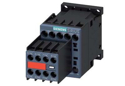
Contactor relays are switching devices for control and auxiliary circuits and are used for controlling, signaling and locking switching devices and switchgear. The SIRIUS 3RH2 contactor relays come with standard-compliant connection designations and a connection system that saves both time and installation overhead. This makes them particularly suitable for practical applications.
3RH2 contactor relays and size S00 motor contactors are the same size and have an identical design – a significant advantage, particularly with regard to the accessories.
They are designed for AC or DC operation and are available with screw or spring-type terminals. The basic version of the contactor relays is a 4‑pole design which can be extended up to eight poles by means of snap-on auxiliary switch blocks.
![]()
Technical data specific to Contactor relay, 6 NO + 2 NC, 125 V DC, Size S00, Ring cable lug connection, Captive auxiliary switch
| Product brand name | SIRIUS | |||||||||||||||||||||||||
| Product designation | Auxiliary contactor | |||||||||||||||||||||||||
| Product type designation | 3RH2 | |||||||||||||||||||||||||
| General technical data | ||||||||||||||||||||||||||
| Size of contactor | S00 | |||||||||||||||||||||||||
| Product extension | ||||||||||||||||||||||||||
| ● Auxiliary switch | No | |||||||||||||||||||||||||
| Insulation voltage | ||||||||||||||||||||||||||
| ● with degree of pollution 3 rated value | 690 V | |||||||||||||||||||||||||
| Degree of pollution | 3 | |||||||||||||||||||||||||
| Surge voltage resistance rated value | 6 kV | |||||||||||||||||||||||||
| Protection class IP | ||||||||||||||||||||||||||
| ● on the front | IP00 | |||||||||||||||||||||||||
| Shock resistance at rectangular impulse | ||||||||||||||||||||||||||
| ● at DC | 10g / 5 ms, 5g / 10 ms | |||||||||||||||||||||||||
| Shock resistance with sine pulse | ||||||||||||||||||||||||||
| ● at DC | 15g / 5 ms, 8g / 10 ms | |||||||||||||||||||||||||
| Mechanical service life (switching cycles) | ||||||||||||||||||||||||||
| ● of contactor typical | 10 000 000 | |||||||||||||||||||||||||
| Reference code acc. to DIN EN 81346-2 | K | |||||||||||||||||||||||||
| Reference code acc. to DIN EN 61346-2 | K | |||||||||||||||||||||||||
| Ambient conditions | ||||||||||||||||||||||||||
| Installation altitude at height above sea level | ||||||||||||||||||||||||||
| ● maximum | 2 000 m | |||||||||||||||||||||||||
| Ambient temperature | ||||||||||||||||||||||||||
| ● during operation | -25 … +60 °C | |||||||||||||||||||||||||
| ● during storage | -55 … +80 °C | |||||||||||||||||||||||||
| Main circuit | ||||||||||||||||||||||||||
| No-load switching frequency | ||||||||||||||||||||||||||
| ● at AC | 10 000 1/h | |||||||||||||||||||||||||
| ● at DC | 10 000 1/h | |||||||||||||||||||||||||
| Control circuit/ Control | ||||||||||||||||||||||||||
| Type of voltage of the control supply voltage | DC | |||||||||||||||||||||||||
| Control supply voltage at DC | ||||||||||||||||||||||||||
| ● rated value | 125 V | |||||||||||||||||||||||||
| Operating range factor control supply voltage rated value of magnet coil at DC | ||||||||||||||||||||||||||
| ● initial value | 0.8 | |||||||||||||||||||||||||
| ● Full-scale value | 1.1 | |||||||||||||||||||||||||
| Closing power of magnet coil at DC | 4 W | |||||||||||||||||||||||||
| Holding power of magnet coil at DC | 4 W | |||||||||||||||||||||||||
| Closing delay | ||||||||||||||||||||||||||
| ● at DC | 30 … 100 ms | |||||||||||||||||||||||||
| Opening delay | ||||||||||||||||||||||||||
| ● at DC | 7 … 13 ms | |||||||||||||||||||||||||
| Arcing time | 10 … 15 ms | |||||||||||||||||||||||||
| Auxiliary circuit | ||||||||||||||||||||||||||
| Number of NC contacts for auxiliary contacts | 2 | |||||||||||||||||||||||||
| ● instantaneous contact | 2 | |||||||||||||||||||||||||
| Number of NO contacts for auxiliary contacts | 6 | |||||||||||||||||||||||||
| ● instantaneous contact | 6 | |||||||||||||||||||||||||
| Identification number and letter for switching elements | 62 E | |||||||||||||||||||||||||
| Operating current at AC-12 maximum | 10 A | |||||||||||||||||||||||||
| Operating current at AC-15 | ||||||||||||||||||||||||||
| ● at 230 V rated value | 6 A | |||||||||||||||||||||||||
| ● at 400 V rated value | 3 A | |||||||||||||||||||||||||
| ● at 500 V rated value | 2 A | |||||||||||||||||||||||||
| ● at 690 V rated value | 1 A | |||||||||||||||||||||||||
| Operating current at 1 current path at DC-12 | ||||||||||||||||||||||||||
| ● at 24 V rated value | 10 A | |||||||||||||||||||||||||
| ● at 110 V rated value | 3 A | |||||||||||||||||||||||||
| ● at 220 V rated value | 1 A | |||||||||||||||||||||||||
| ● at 440 V rated value | 0.3 A | |||||||||||||||||||||||||
| ● at 600 V rated value | 0.15 A | |||||||||||||||||||||||||
| Operating current with 2 current paths in series at DC-12 | ||||||||||||||||||||||||||
| ● at 24 V rated value | 10 A | |||||||||||||||||||||||||
| ● at 60 V rated value | 10 A | |||||||||||||||||||||||||
| ● at 110 V rated value | 4 A | |||||||||||||||||||||||||
| ● at 220 V rated value | 2 A | |||||||||||||||||||||||||
| ● at 440 V rated value | 1.3 A | |||||||||||||||||||||||||
| ● at 600 V rated value | 0.65 A | |||||||||||||||||||||||||
| Operating current with 3 current paths in series at DC-12 | ||||||||||||||||||||||||||
| ● at 24 V rated value | 10 A | |||||||||||||||||||||||||
| ● at 60 V rated value | 10 A | |||||||||||||||||||||||||
| ● at 110 V rated value | 10 A | |||||||||||||||||||||||||
| ● at 220 V rated value | 3.6 A | |||||||||||||||||||||||||
| ● at 440 V rated value | 2.5 A | |||||||||||||||||||||||||
| ● at 600 V rated value | 1.8 A | |||||||||||||||||||||||||
| Operating frequency at DC-12 maximum | 1 000 1/h | |||||||||||||||||||||||||
| Operating current at 1 current path at DC-13 | ||||||||||||||||||||||||||
| ● at 24 V rated value | 6 A | |||||||||||||||||||||||||
| ● at 110 V rated value | 1 A | |||||||||||||||||||||||||
| ● at 220 V rated value | 0.3 A | |||||||||||||||||||||||||
| ● at 440 V rated value | 0.14 A | |||||||||||||||||||||||||
| ● at 600 V rated value | 0.1 A | |||||||||||||||||||||||||
| Operating current with 2 current paths in series at DC-13 | ||||||||||||||||||||||||||
| ● at 24 V rated value | 10 A | |||||||||||||||||||||||||
| ● at 60 V rated value | 3.5 A | |||||||||||||||||||||||||
| ● at 110 V rated value | 1.3 A | |||||||||||||||||||||||||
| ● at 220 V rated value | 0.9 A | |||||||||||||||||||||||||
| ● at 440 V rated value | 0.2 A | |||||||||||||||||||||||||
| ● at 600 V rated value | 0.1 A | |||||||||||||||||||||||||
| Operating current with 3 current paths in series at DC-13 | ||||||||||||||||||||||||||
| ● at 24 V rated value | 10 A | |||||||||||||||||||||||||
| ● at 60 V rated value | 4.7 A | |||||||||||||||||||||||||
| ● at 110 V rated value | 3 A | |||||||||||||||||||||||||
| ● at 220 V rated value | 1.2 A | |||||||||||||||||||||||||
| ● at 440 V rated value | 0.5 A | |||||||||||||||||||||||||
| ● at 600 V rated value | 0.26 A | |||||||||||||||||||||||||
| Operating frequency at DC-13 maximum | 1 000 1/h | |||||||||||||||||||||||||
| Design of the miniature circuit breaker | ||||||||||||||||||||||||||
| ● for short-circuit protection of the auxiliary circuit up to 230 V | C characteristic: 6 A; 0.4 kA | |||||||||||||||||||||||||
| Contact reliability of auxiliary contacts | 1 faulty switching per 100 million (17 V, 1 mA) | |||||||||||||||||||||||||
| UL/CSA ratings | ||||||||||||||||||||||||||
| Contact rating of auxiliary contacts according to UL | A600 / Q600 | |||||||||||||||||||||||||
| Short-circuit protection | ||||||||||||||||||||||||||
| Design of the fuse link | ||||||||||||||||||||||||||
| ● for short-circuit protection of the auxiliary switch required | fuse gL/gG: 10 A | |||||||||||||||||||||||||
| Installation/ mounting/ dimensions | ||||||||||||||||||||||||||
| Mounting position | +/-180° rotation possible on vertical mounting surface; can be tilted forward and backward by +/- 22.5° on vertical mounting surface | |||||||||||||||||||||||||
| Mounting type | screw and snap-on mounting onto 35 mm standard mounting rail | |||||||||||||||||||||||||
| Height | 57.5 mm | |||||||||||||||||||||||||
| Width | 45 mm | |||||||||||||||||||||||||
| Depth | 117 mm | |||||||||||||||||||||||||
| Required spacing | ||||||||||||||||||||||||||
| ● with side-by-side mounting | ||||||||||||||||||||||||||
| — forwards | 10 mm | |||||||||||||||||||||||||
| — upwards | 10 mm | |||||||||||||||||||||||||
| — downwards | 10 mm | |||||||||||||||||||||||||
| — at the side | 0 mm | |||||||||||||||||||||||||
| ● for grounded parts | ||||||||||||||||||||||||||
| — forwards | 10 mm | |||||||||||||||||||||||||
| — upwards | 10 mm | |||||||||||||||||||||||||
| — at the side | 6 mm | |||||||||||||||||||||||||
| — downwards | 10 mm | |||||||||||||||||||||||||
| ● for live parts | ||||||||||||||||||||||||||
| — forwards | 10 mm | |||||||||||||||||||||||||
| — upwards | 10 mm | |||||||||||||||||||||||||
| — downwards | 10 mm | |||||||||||||||||||||||||
| — at the side | 6 mm | |||||||||||||||||||||||||
| Connections/ Terminals | ||||||||||||||||||||||||||
| Type of electrical connection | ||||||||||||||||||||||||||
| ● for auxiliary and control current circuit | ring cable connection | |||||||||||||||||||||||||
| Safety related data | ||||||||||||||||||||||||||
| B10 value | ||||||||||||||||||||||||||
| ● with high demand rate acc. to SN 31920 | 1 000 000; With 0.3 x Ie | |||||||||||||||||||||||||
| Proportion of dangerous failures | ||||||||||||||||||||||||||
| ● with low demand rate acc. to SN 31920 | 40 % | |||||||||||||||||||||||||
| ● with high demand rate acc. to SN 31920 | 73 % | |||||||||||||||||||||||||
| Failure rate [FIT] | ||||||||||||||||||||||||||
| ● with low demand rate acc. to SN 31920 | 100 FIT | |||||||||||||||||||||||||
| Product function | ||||||||||||||||||||||||||
| ● positively driven operation acc. to IEC 60947-5-1 | Yes | |||||||||||||||||||||||||
| T1 value for proof test interval or service life acc. to IEC 61508 | 20 y | |||||||||||||||||||||||||
| Certificates/ approvals | ||||||||||||||||||||||||||
|
||||||||||||||||||||||||||
![]()
https://support.industry.siemens.com/cs/pd/445960?pdti=td&dl=en&pnid=16187&lc=en-WW
https://mall.industry.siemens.com/mall/en/WW/Catalog/Products/8210404?tree=CatalogTree#More information


