NovaTech: Modular Distributed Event Recorders
September 15, 2020
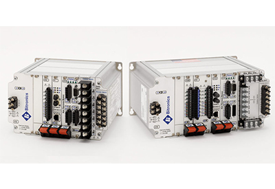
The Bitronics M871 (Single Line, Dual Bus) and M872 (Dual Line, Dual Bus) IEDs provide a complete solution for monitoring and recording in substation applications. They provide a scalable, low-cost distributed disturbance recording solution that meets all three PRC-002 requirements in a single unit and supports peer-to-peer GOOSE messaging for cross-triggering without hard-wired contacts. The M871 and M872 complement relays by providing independent, higher-fidelity waveform capture with two disturbance recording modes and trend recording not typically found even in the most advanced digital relays.
They also provide features such as fault location and SCADA communications that can automate a substation where electro-mechanical relays are used. The ability to support multiple physical links and protocols simultaneously allows easy integration in retrofit applications or newer substation automation projects. The M871 and M872 serve as a front-end to SCADA while also providing system-wide access to important substation data. Multi-mode recording and high speed, high accuracy measurements allow analysis of Network faults, reactions of protective devices, dynamic response of the network, long-term trends, revenue readings at interties, substation equipment performance.
The Bitronics M571 and M572 offer a similar function to the M871/M872, but in a fixed, rather than modular design, and with fewer options. The M571 and M572 are available for sale through 2015, but will become obsolete after that. The M871/M872 are available as replacements for automation and recording applications, while the PowerPlex II can be used as an Ethernet transducer where accurate, high-speed measurements are needed, and for direct connect up to 600 V ac line-to-line.
![]()
X = standard, O = optional
| Feature | M871 | M872 |
|---|---|---|
| Volts and Amps | X | X |
| 2000+ High Accuracy Measurements including: Power, Energy, Frequency, Demand, Harmonics, K-Factor, Flicker, Impedance & Symmetrical Components | X | X |
| Detached Displays | O | O |
| 0.2% Revenue Accuracy | X | X |
| 0.1% Voltage and Current Accuracy | X | X |
| 4ms RMS Updates | X | X |
| Wide input frequency range of 15-70 Hz | X | X |
| RJ45 Ethernet | O | O |
| Fiber Ethernet | O | O |
| Dual 3-Phase Current Inputs | X | |
| Directly Monitored Neutral Current | X | |
| DNP/Modbus over TCP/IP | X | X |
| IEC 61850 with GOOSE over TCP/IP | X | X |
| Modbus Plus | O | O |
| Multiple Simultaneous Protocol Communications | X | X |
| One RS-232 and three configurable RS-232/RS-485 ports | X | X |
| Trend Recording | X | X |
| Sequence of Event Recording | X | X |
| Disturbance and Event Capture | X | X |
| Non-Volatile Memory | X | X |
| Distance-to-Fault | X | X |
| Battery Voltage Inputs | X | |
| Wide Range Universal Auxiliary Power Supply | X | X |
| Digital and Analog I/O | O | O |
Specifications
Measurement and Signal Inputs of the M871
- – Measurements including volts, currents, power, energy, frequency, demand, individual and total harmonics, K-factor, current & voltage unbalance, flicker, impedance and symmetrical components
- – Current input for the S10 Signal Input module has a nominal range of 0 – 5A ac, linear to 100A ac symmetrical rms at all rated temperatures.
- – Current input for the S11 Signal Input has a nominal range of 0 – 1A ac or 0 – 5A ac, linear to 20A ac symmetrical rms at all rated temperatures and the 0 – 5A ac range is compliant to IEC 60687 and ANSI C12.20 revenue class accuracy of 0.2%
- – Current input for the S12 Signal Input has a nominal range of 0 – 1A ac, linear to 4A ac at all rated temperatures and is compliant to IEC60687 and ANSI C12.20 revenue class accuracy of 0.2%
- – The AC voltage inputs are intended for use on nominal system voltages up to 480V ac rms phase-phase (277V ac RMS phase-neutral)
- – Two auxiliary AC/DC voltage inputs are intended for use on nominal system voltages up to 480V ac rms phase-phase (277V ac RMS phase-neutral), and on DC system voltages up to 250V dc
- – Transducer input option that provides eight inputs in 0-1mA, 4-20mA or 0-10V ranges
Measurement and Signal Inputs of the M872
- – Measurements including volts, currents, power, energy, frequency, demand, individual and total harmonics, K-factor, current & voltage unbalance, flicker, impedance and symmetrical components
- – Current input for the S13 Signal Input module has a nominal range of 0 – 5A ac, linear to 100A ac symmetrical rms at all rated temperatures.
- – Current input for the S14 Signal Input has a range of 0 -1A ac or 0 – 5A ac, linear to 20A ac symmetrical rms at all rated temperatures and the 0 – 5A ac range is compliant to IEC 60687 and ANSI C12.20 revenue class accuracy of 0.2%
- – Current input for the S15 Signal Input has a nominal range of 0 – 1A ac, linear to 4A ac at all rated temperatures and is compliant to IEC 60687 and ANSI C12.20 revenue class accuracy of 0.2%
- – The AC voltage inputs are intended for use on nominal system voltages up to 480V ac rms phase-phase (277V ac RMS phase-neutral)
- – Transducer input option that provides eight inputs in 0 – 1mA, 4 – 20mA or 0 – 10V ranges
Recording
- – Waveform recorders have up to 14 assignable analog channels with adjustable sampling rates of 32 or 64 and 128 samples per cycle. In the M871, the sampling rate can increase to 256 samples per cycle if only 7 channels are connected. Pre-trigger and post trigger size is assignable. Digital inputs can be included in the recording. Stored in COMTRADE format.
- – The Disturbance recorders have up to 64 assignable measurement channels with a selectable time resolution from one cycle to sixty seconds. Pre-trigger and post trigger size is assignable. Stored in COMTRADE format.
- – The trend recorders have up to 230 selectable parameters with time resolution of one minute to twelve hours. Choice of instantaneous or min, max and average.
- – Sequence of Event recording has 5,000 event record storage with events time stamped to 1 microsecond. Stored in Text format.
- – All triggers have three trigger modes
- – Event triggering with logic includes hysteresis from any analog threshold value, rate-of-change of analog value, digital input, or “virtual” input (GOOSE message)
- – Automatic event notification
Communications
- – One RS-232 and three configurable RS-232/RS-485 ports supporting baud rates from 9600 to 115200
- – Optional 10BaseT/100BaseTX or added 100Mb fiber-optic port (100BaseFX)
- – Supports protocols: DNP3 Level 2, DNP3 TCP/IP, DNP3/UDP, Modbus RTU, Modbus TCP/IP, ZMODEM, FTP, telnet, UCA2 (including GOOSE messaging), IRIG-B, SNTP and IEC 61850
- – Supports Modbus Plus (with optional P20 module)
- – An IRIG-B port adapter with BNC connector is available that accepts modulated signals and interfaces directly to one of the serial ports.
- – Automatic event notification via Ethernet or serial media
Modular Design
The M871 uses a modular design based on the Compact PCI bus. There are three chassis sizes:
- – Short Chassis, with 3 optional module slots at 8.5” wide. Refer to ORDER GUIDE 200.
- – Intermediate Chassis with 5 optional module slots at 11.65” wide. Refer to ORDER GUIDE 202.
- – Long Chassis with 6 optional module slots at 13.45” wide. Refer to ORDER GUIDE 201.
The M872 uses a modular design based on the Compact PCI bus. There are two chassis sizes:
- – Intermediate Chassis with 5 optional module slots at 11.65” wide. Refer to ORDER GUIDE 203.
- – Long Chassis with 6 optional module slots at 13.45” wide. Refer to ORDER GUIDE 204.
An M871 must have the following modules:
- – V10 universal power supply module, rated 20-300V dc/55-275V ac.
- – H12 host processor and A10 analog processor module consisting of a 486 Processor, 32-bit DSP, 16-bit A/D converter and RAM and nonvolatile memory (standard is 256Mb, optional 512Mb or 1GB)
- – One signal input module. There are choices of an S10, S11 or S12 signal input module.
An M872 must the following modules:
- – V10 universal power supply module, rated 20-300V dc/ 55-275V ac.
- – H12 host processor and A10 analog processor module consisting of a 486 Processor, 32-bit DSP, 16-bit A/D converter and RAM and nonvolatile memory
- – One signal input module. There are choices of an S13, S14 or S15 signal input module.
The choices of optional modules and their max quantity depend on the chassis size and what module space is available.
- – E1 or E3 Ethernet Options (1 Max) attached to H12 host processor
- – P20 Modbus Plus Module (1 Max)
- – P30A Digital I/O Module 4-8 DI/ 0-4 DO (6 Max)
- – P31 Digital I/O Module 12-16 DI/ 0-4 DO (3 Max) that requires two slots
- – P40 Transducer Input Module 8 AI (5 Max)
![]()
https://www.novatechweb.com/power-measurement/distributed-event-recorders-m871-m872/


